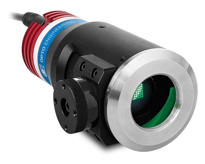
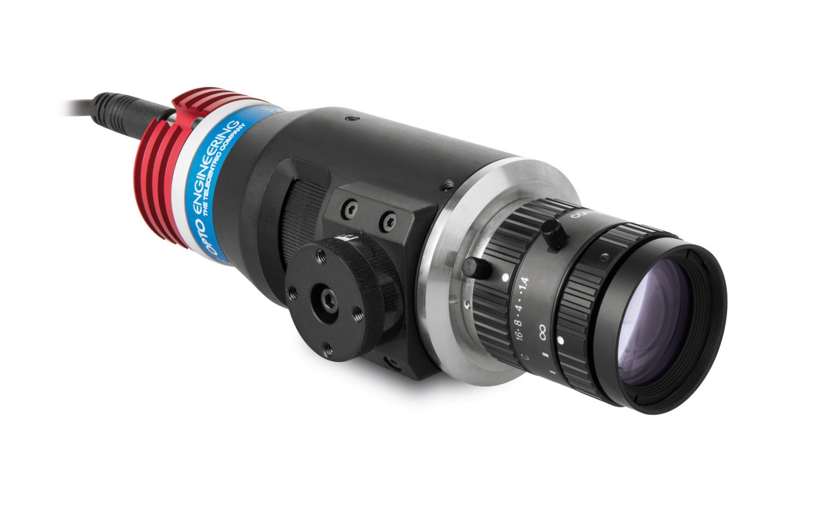
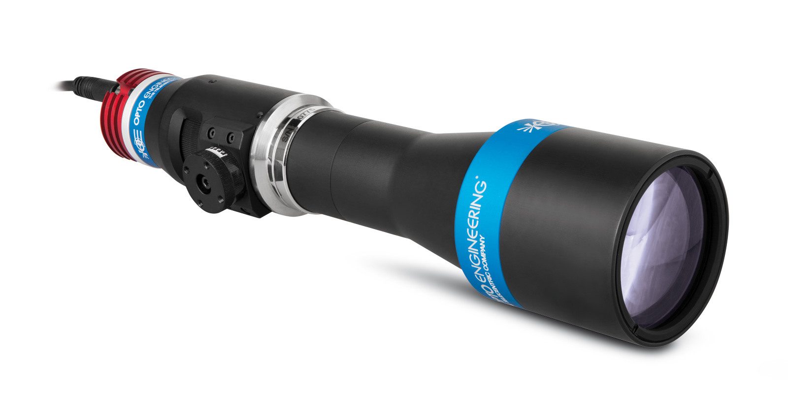
LTPRSMHP3W series
3W tilting LED pattern projectors

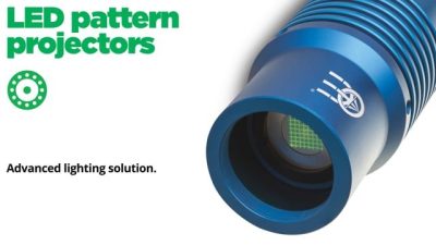
Key advantages
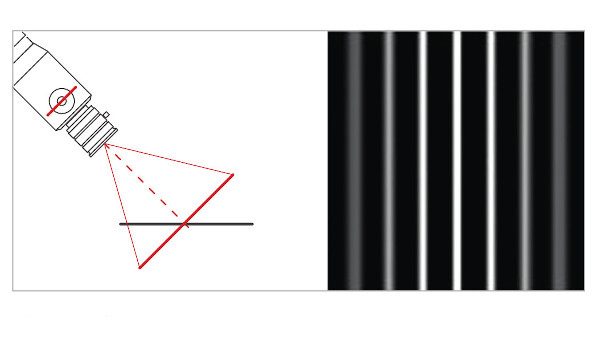
- Scheimpflug tilt adjustment compatible with C-mount optics
Focus is maintained even when the pattern is tilted. - Light condenser focusing mechanism
For excellent optical coupling and light throughput. - Enhanced optical power
High numerical aperture condenser lens.
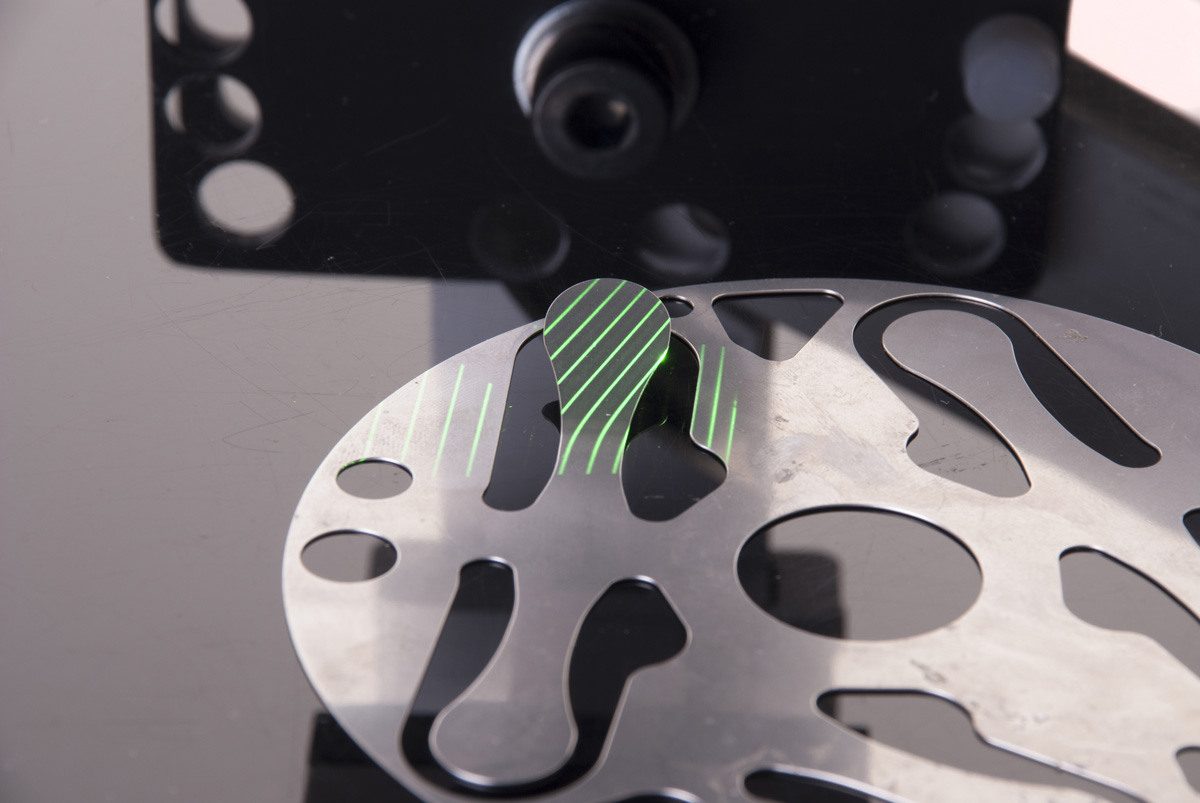
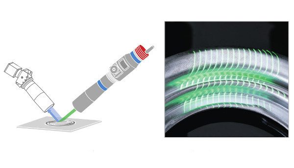
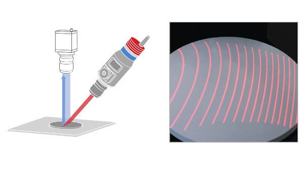
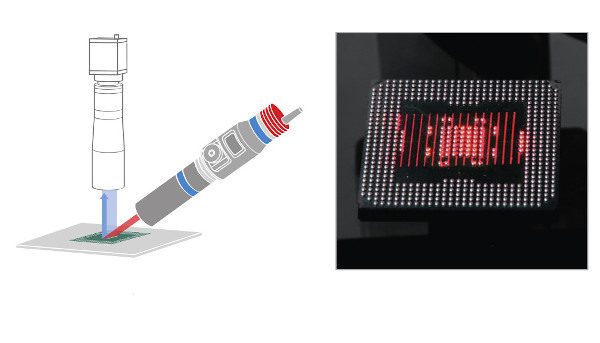
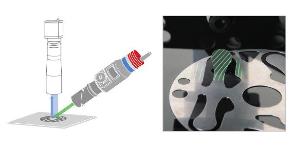
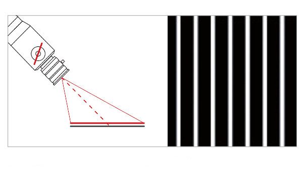
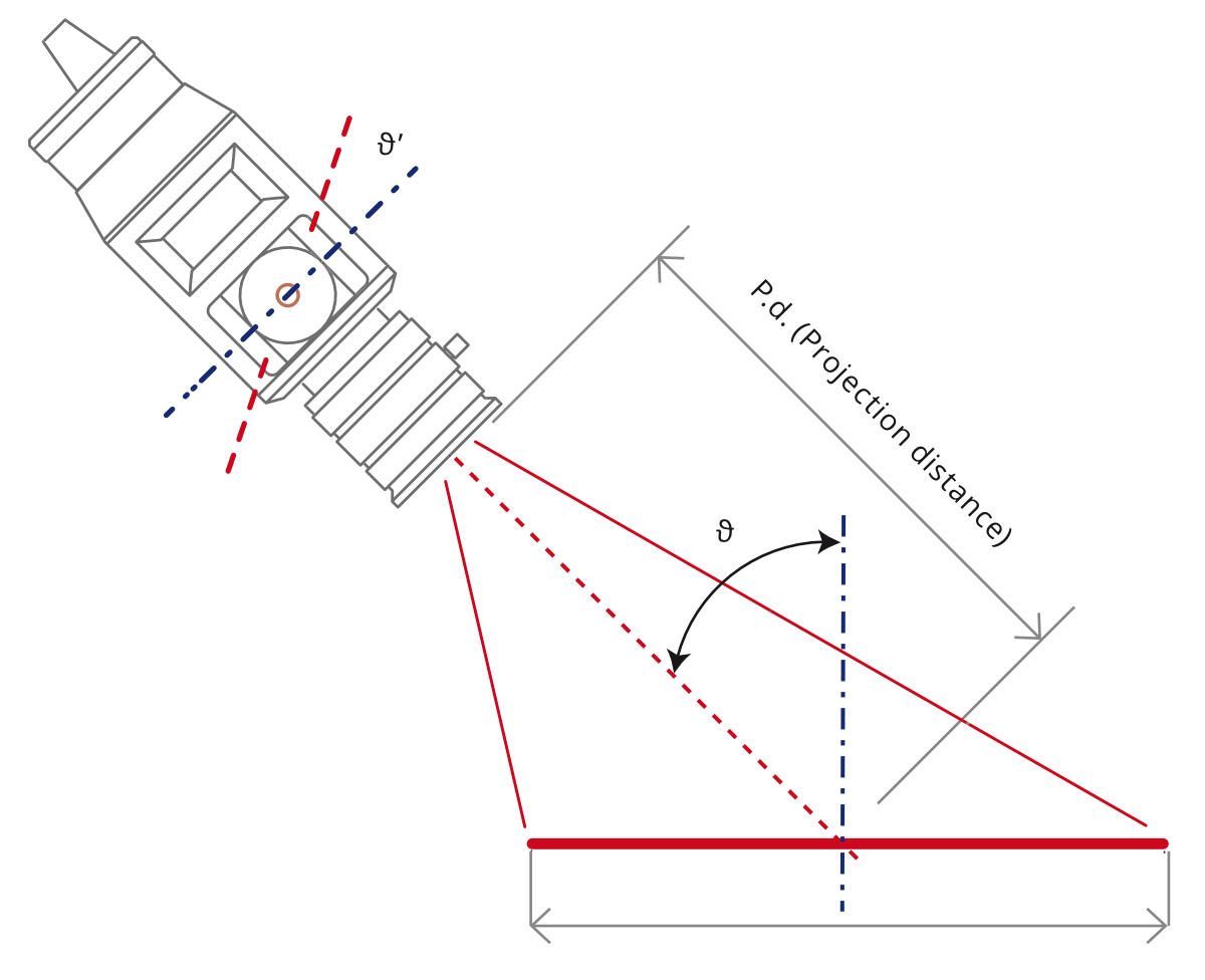
LTPRSMHP3W series are LED pattern projectors specifically designed for the most demanding 3D profiling and measurement applications. Triangulation techniques require that structured light is directed onto a sample at a considerable angle from vertical. Tilting the light source pattern becomes essential to ensure that the patterned light is properly focused across the entire sample surface.
LTPRSMHP3W pattern projectors integrate a precision tilting mechanism based on the Scheimpflug condition. This ensures that focus is maintained across the entire part, and reconstruction of the 3d surface is as accurate as possible. Moreover, the internal focus mechanism offers the maximum optical throughput.
Notes
- With a 35 mm lens, F/N 1.4 at 100 mm working distance without projection pattern at maximum driving current. Estimated value.
- To pulse LTRPSMHP3W, models built-in electronics must be bypassed in order to drive the LED directly.
- Tolerance ± 10%
- Max continuous LED driving current is supplied through the built-in electronics. No external controller is required.
- At max forward current. Tolerance is ± 0.06V on forward voltage measurements
- At pulse width <= 10 ms and duty cycle <= 10%. Built-in electronics board must be bypassed (see tech info)
- At 55 °C, 720mA.
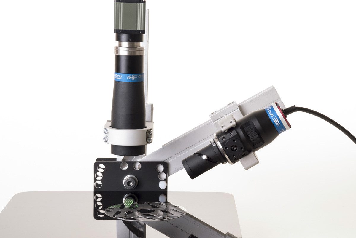
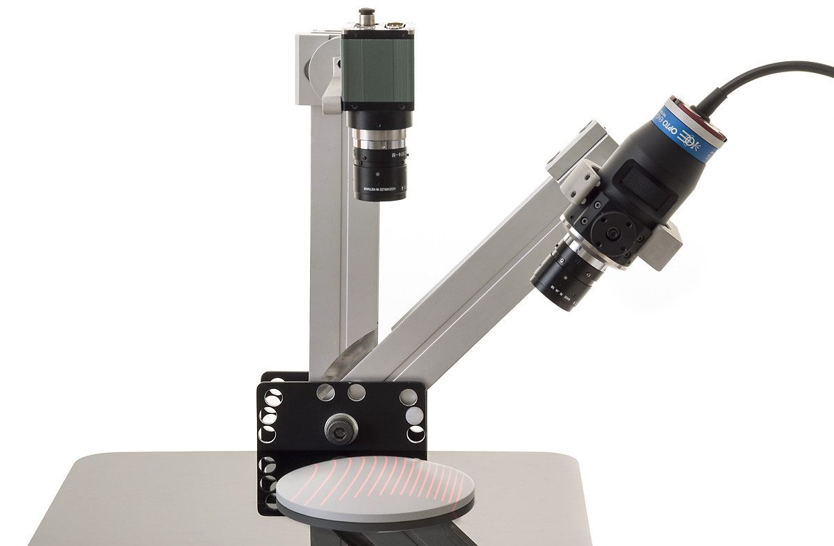
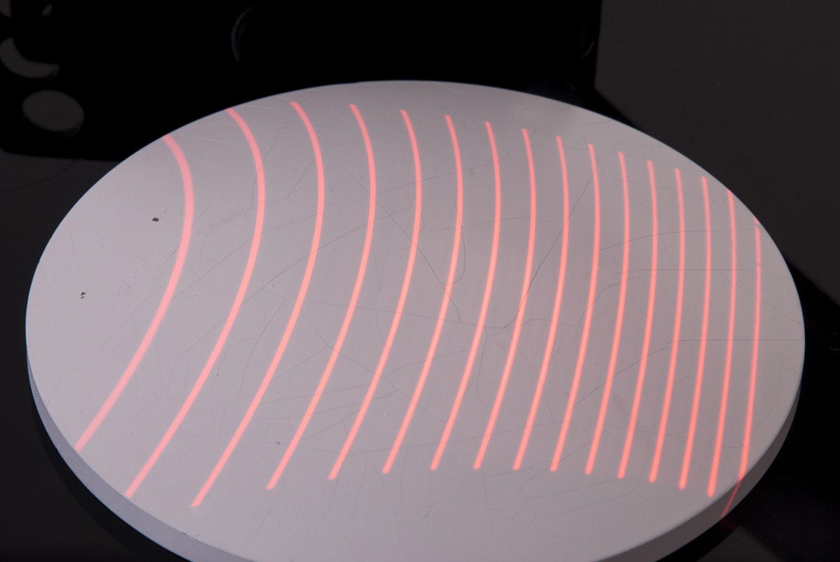
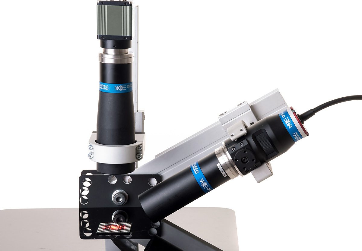
Examples of setup applications
Comparing LED pattern projectors
Model |
Integrated driver |
Passive cooling |
Compact shape |
5-pin M12 connector |
Built-in temperature sensor |
Continuous mode | Strobe mode | Projection lens | Power |
LTPRHP3W |
✓* |
✓ | ✓ |
✕ |
✕ |
✓ | ✓** | Up to 2/3" | Low |
LTPRSMHP3W |
✓* |
✓ | ✓ |
✕ |
✕ |
✓ | ✓** | Up to 2/3" | Low |
LT2PRXP |
✓ |
✓ |
✕ |
✓ |
✓ |
✓ | ✓ | Up to 1.1" | Medium |
LT2PRXP-C |
✕ | ✓ |
✓ |
✓ |
✓ |
✕ | ✓** | Up to 1.1" | Medium |
LT2PRUP |
✓ |
✓ |
✕ |
✓ |
✓ |
✓ | ✓ | Up to 1.1" | High |
| * Controls only continuous operation mode | |||||||||
| ** Only with external driver | |||||||||
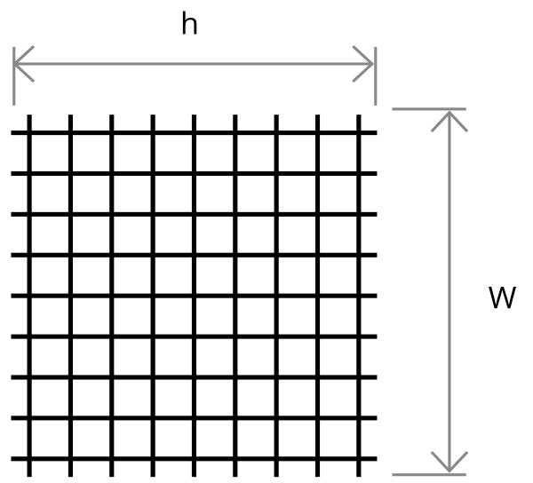
LTPRSM series units can be interfaced with any type of optics, but the best results are achieved with bi-telecentric lenses.
The projection area is undistorted since tilting the pattern causes a linear extension along only one direction.
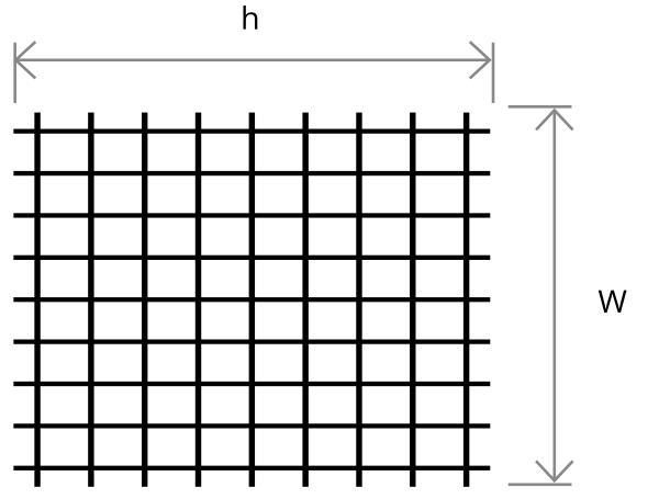
Excellent results can also be obtained with zero distortion macro lenses; here, the magnification changes along both axes, but image resolution and distortion still easily allows 3D reconstruction.
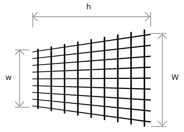
With non bi-telecentric lenses, a square pattern becomes a trapezoid in the projection plane, whose parallel sides are indicated as “w” and “W” in the drawings below.
The projection area shown in the chart are also a good approximation for standard C-mount lenses used as macro lenses (eventually equipped with spacers).
Projection area with bi-telecentric lenses (TC series)
| ϑ = 0° | ϑ = 15° | ϑ = 30° | ϑ = 45° | ||||||
| Part number |
Projection distance |
Projection area |
Pattern tilt |
Projection area |
Pattern tilt |
Projection area |
Pattern tilt |
Projection area |
Pattern tilt |
| P.d. | W x h | ϑ’ | W x h | ϑ’ | W x h | ϑ’ | W x h | ϑ’ | |
| (mm) | (mm x mm) | (deg) | (mm x mm) | (deg) | (mm x mm) | (deg) | (mm x mm) | (deg) | |
| TC23009 | 63.3 | 8.0 x 8.0 | 0 | 8.0 x 8.0 | 15 | 8.0 x 8.0 | 30.0 | 8.0 x 8.0 | 45.0 |
| TC23016 | 45.3 | 15.2 x 15.2 | 0 | 15.2 x 15.4 | 8.01 | 15.2 x 16.8 | 17.0 | 15.2 x 20.0 | 27.8 |
| TC23024 | 69.2 | 22.9 x 22.9 | 0 | 22.9 x 23.6 | 5.4 | 22.9 x 26.0 | 11.4 | 22.9 x 30.5 | 19.3 |
| TC23036 | 103.5 | 32.9 x 32.9 | 0 | 32.9 x 34.0 | 3.7 | 32.9 x 37.7 | 8.0 | 32.9 x 45.3 | 13.6 |
| TC23048 | 134.6 | 43.3 x 43.3 | 0 | 43.3 x 44.7 | 2.8 | 43.3 x 49.8 | 6.1 | 43.3 x 60.3 | 10.5 |
| TC23056 | 159.3 | 51.0 x 51.0 | 0 | 51.0 x 52.8 | 2.4 | 51.0 x 58.6 | 5.01 | 51.0 x 71.3 | 8.8 |
| TC23064 | 182.0 | 58.2 x 58.2 | 0 | 58.2 x 60.3 | 2.1 | 58.2 x 67.1 | 4.5 | 58.2 x 81.7 | 7.8 |
| TC23080 | 227.0 | 72.7 x 72.7 | 0 | 72.7 x 73.8 | 1.7 | 72.7 x 83.6 | 3.6 | 72.7 x 102.0 | 6.3 |
| TC23096 | 279.0 | 85.6 x 85.6 | 0 | 85.6 x 88.6 | 1.04 | 85.6 x 98.7 | 3.1 | 85.6 x 120.9 | 5.3 |
Projection area with macro (MC3-03x and MC series) and standard lenses
| ϑ = 0° | ϑ = 15° | ϑ = 30° | ϑ = 45° | |||||||||||
| Mag. | Projection distance |
Projection area |
Pattern tilt |
Projection area |
Pattern tilt |
Projection area |
Pattern tilt |
Projection area |
Pattern tilt |
Suggested Macro lenses |
||||
| w | (W) x h | ϑ’ | w | (W) x h | ϑ’ | w | (W) x h | ϑ’ | w | (W) x h | ϑ’ | |||
| (x) | (mm) | (mm) | (mm x mm) | (deg) | (mm) | (mm x mm) | (deg) | (mm) | (mm x mm) | (deg) | (mm) | (mm x mm) | (deg) | |
| 1.00 | 46.0 | 8.0 | (8.0) x 8.0 | 0 | 7.7 | (8.3) x 8.0 | 15.0 | 7.5 | (8.6) x 8.1 | 30.0 | 7.3 | (8.9) x 8.1 | 45.0 | MC3-03X, MC100X |
| 0.75 | 48.0 | 10.7 | (10.7) x 10.7 | 0 | 10.3 | (11.1) x 10.9 | 11.4 | 10.0 | (11.6) x 11.4 | 23.5 | 9.6 | (12.1) x 12.3 | 37.0 | MC3-03X, MC075X |
| 0.50 | 60.0 | 16.1 | (16.1) x 16.1 | 0 | 15.5 | (16.7) x 16.5 | 7.6 | 14.9 | (17.5) x 17.9 | 16.2 | 14.3 | (18.4) x 20.7 | 26.7 | MC3-03X, MC050X |
| 0.33 | 92.0 | 24.3 | (24.3) x 24.3 | 0 | 23.4 | (25.3) x 25.1 | 5.1 | 22.5 | (26.5) x 27.8 | 10.8 | 21.4 | (28.1) x 33.3 | 18.3 | MC3-03X, MC033X |
| 0.20 | 136.0 | 40.1 | (40.1) x 40.1 | 0 | 38.6 | (41.6) x 42.1 | 3.1 | 37.0 | (43.6) x 46.2 | 6.6 | 35.1 | (46.6) x 56.8 | 11.4 | MC3-03X |
| 0.10 | 275.0 | 79.5 | (79.5) x 79.5 | 0 | 76.6 | (82.6) x 82.4 | 1.6 | 73.5 | (86.6) x 92.3 | 3.4 | 69.6 | (92.6) x 114.2 | 5.8 | MC3-03X |
About projection patterns
The projection pattern placed inside the unit can be changed and integrated with ease: just remove the C-mount adaptor by loosening the set screws and fix the pattern by screwing the retaining ring.
Different types of stripe and grid patterns are available; the chart below shows the line thickness (0.05 mm) and the gap between neighboring lines for each pattern type.
When these features are projected, they become 1/M times larger, with “M” being the magnification of the projection lens. The number of lines mentioned after each part number indicates the number of features on the active area of the pattern.
| With LTPRHP, LTPRXP and LTPRUP projectors (circular aperture) |
With LTPRSMHP projectors (square aperture) |
||||||||||||||
|---|---|---|---|---|---|---|---|---|---|---|---|---|---|---|---|
| Format | Process | Substrate | Coating | Line spacing |
Thickness | Geometrical accuracy |
Edge sharpness |
Active area |
Number of lines |
Max line length |
Active area |
Number of lines |
Line length |
||
| (mm) | (mm) | (µm) | (µm) | (mm) | (mm) | (mm x mm) | (mm) | ||||||||
| PT00000100P | Line | Photolitography | Soda lime glass | Chrome | - | 0.05 | 2 | 1.4 | 11 | 1 | 11 | 8 x 8 | 1 | 8 | Quote |
| PT00000100L | Line | Laser engraving | Borofloat glass | Dichroic mirror | - | 0.5 | 50 | 50 | 11 | 1 | 11 | 8 x 8 | 1 | 8 | Quote |
| PT00000200P | Cross | Photolitography | Soda lime glass | Chrome | - | 0.05 | 2 | 1.4 | 11 | - | 11 | 8 x 8 | - | 8 | Quote |
| PT00000200L | Cross | Laser engraving | Borofloat glass | Dichroic mirror | - | 0.5 | 50 | 50 | 11 | - | 11 | 8 x 8 | - | 8 | Quote |
| PT00000300P | Stripes | Photolitography | Soda lime glass | Chrome | 0.95 | 0.05 | 2 | 1.4 | 11 | 8 | 7.78 | 8 x 8 | 8 | 7.78 | Quote |
| PT00000300L | Stripes | Laser engraving | Borofloat glass | Dichroic mirror | 0.5 | 0.5 | 50 | 50 | 11 | 8 | 7.78 | 8 x 8 | 8 | 7.78 | Quote |
| PT00000400P | Grid | Photolitography | Soda lime glass | Chrome | 0.95 | 0.05 | 2 | 1.4 | 11 | 8 x 8 | 7.78 | 8 x 8 | 8 x 8 | 7.78 | Quote |
| PT00000400L | Grid | Laser engraving | Borofloat glass | Dichroic mirror | 0.8 | 0.2 | 50 | 50 | 11 | 8 x 8 | 7.78 | 8 x 8 | 8 x 8 | 7.78 | Quote |
| PT00000500P | Edge | Photolitography | Soda lime glass | Chrome | - | - | 2 | 1.4 | 11 | - | - | 8 x 8 | - | - | Quote |
| PT00000500L | Edge | Laser engraving | Borofloat glass | Dichroic mirror | - | - | 50 | 50 | 11 | - | - | 8 x 8 | - | - | Quote |
| PTST050450P | Stripes | Photolitography | Soda lime glass | Chrome | 0.45 | 0.05 | 2 | 1.4 | 11 | 22 | 11 | 8 x 8 | 16 | 8 | Quote |
| PTST050200P | Stripes | Photolitography | Soda lime glass | Chrome | 0.2 | 0.05 | 2 | 1.4 | 11 | 44 | 11 | 8 x 8 | 32 | 8 | Quote |
| PTST050100P | Stripes | Photolitography | Soda lime glass | Chrome | 0.1 | 0.05 | 2 | 1.4 | 11 | 73 | 11 | 8 x 8 | 53 | 8 | Quote |
| PTST050050P | Stripes | Photolitography | Soda lime glass | Chrome | 0.05 | 0.05 | 2 | 1.4 | 11 | 110 | 11 | 8 x 8 | 80 | 8 | Quote |
| PTST010010P | Stripes | Photolitography | Soda lime glass | Chrome | 0.01 | 0.01 | 2 | 1.4 | 11 | 550 | 11 | 8 x 8 | 400 | 8 | Quote |
| PTST020020P | Stripes | Photolitography | Soda lime glass | Chrome | 0.02 | 0.02 | 2 | 1.4 | 11 | 275 | 11 | 8 x 8 | 200 | 8 | Quote |
| PTGR050450P | Grid | Photolitography | Soda lime glass | Chrome | 0.45 | 0.05 | 2 | 1.4 | 11 | 22 x 22 | 11 | 8 x 8 | 16 x 16 | 8 | Quote |
| PTGR050200P | Grid | Photolitography | Soda lime glass | Chrome | 0.2 | 0.05 | 2 | 1.4 | 11 | 44 x 44 | 11 | 8 x 8 | 32 x 32 | 8 | Quote |
| PTGR050100P | Grid | Photolitography | Soda lime glass | Chrome | 0.1 | 0.05 | 2 | 1.4 | 11 | 73 x 73 | 11 | 8 x 8 | 53 x 53 | 8 | Quote |
| PTGR050050P | Grid | Photolitography | Soda lime glass | Chrome | 0.05 | 0.05 | 2 | 1.4 | 11 | 110 x 110 | 11 | 8 x 8 | 80 x 80 | 8 | Quote |
| PTCD010P | Cloud of dots pattern density 10.5% |
Photolitography | Soda lime glass | Chrome | - | - | 2 | 1.4 | 11 | - | - | 8 x 8 | - | - | Quote |
| PTCD020P | Cloud of dots pattern density 20% |
Photolitography | Soda lime glass | Chrome | - | - | 2 | 1.4 | 11 | - | - | 8 x 8 | - | - | Quote |
| PTCD035P | Cloud of dots pattern density 35% |
Photolitography | Soda lime glass | Chrome | - | - | 2 | 1.4 | 11 | - | - | 8 x 8 | - | - | Quote |
Photolitography patterns
| Substrate | Soda lime grass |
| Coating | Chrome |
| Geometrical accuracy | 2 μm |
| Edge sharpness | 1.4 μm |

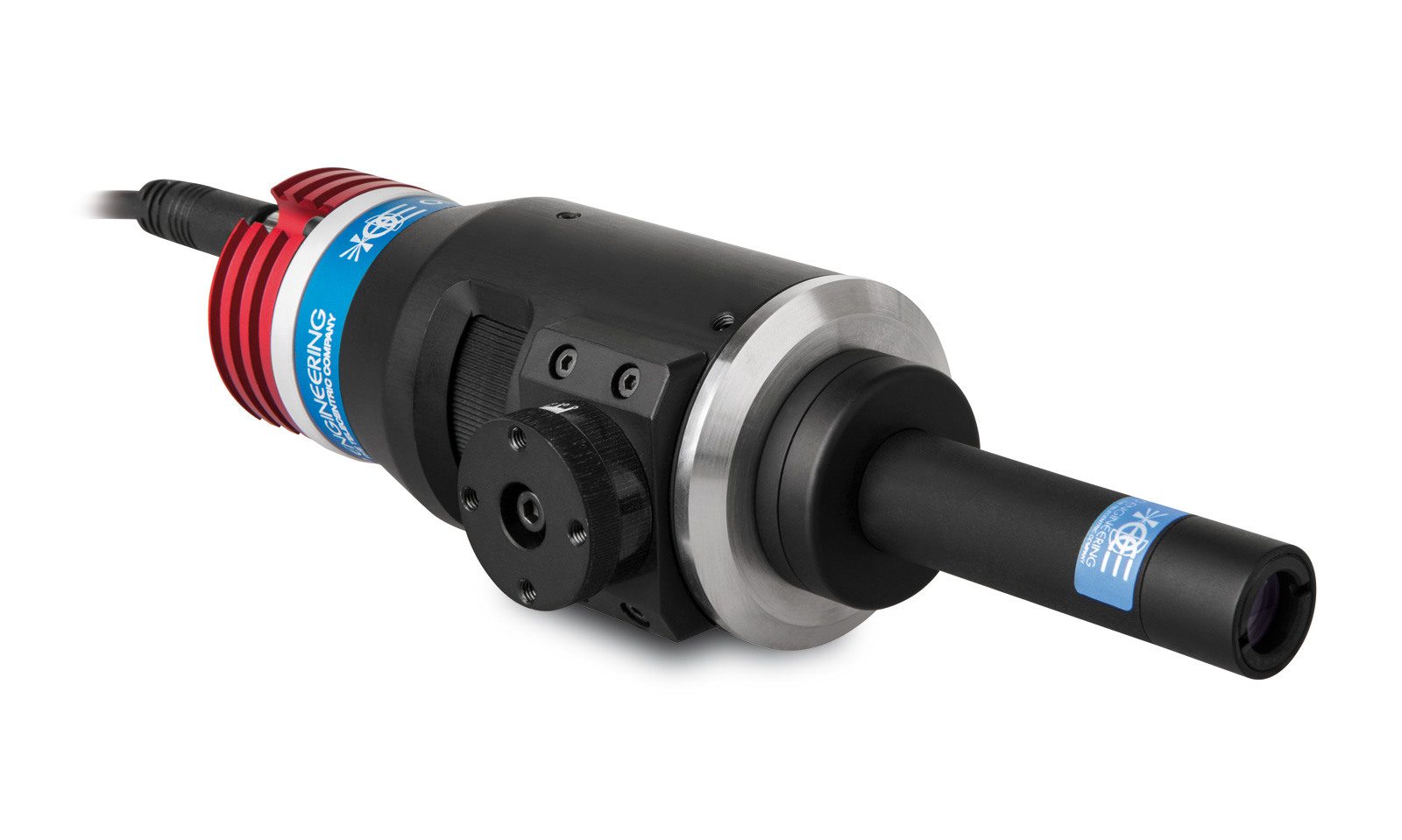
LTPRSM pattern projector with a standard C-mount lens
Bi-telecentric lenses used for both projection and vision
Configuration with zero distortion macro lenses