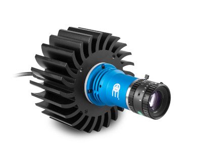
LTPRXP series
10W continuous LED pattern projectors

Key advantages
- LED technology for perfectly sharp edges
Thinner lines, sharper edges and more even illumination than lasers - High power
For minimal sensitivity to ambient light - Wide selection of projection patterns available (custom-made upon request)
Chrome-on-glass patterns with geometrical accuracy down to 2 μm
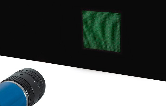
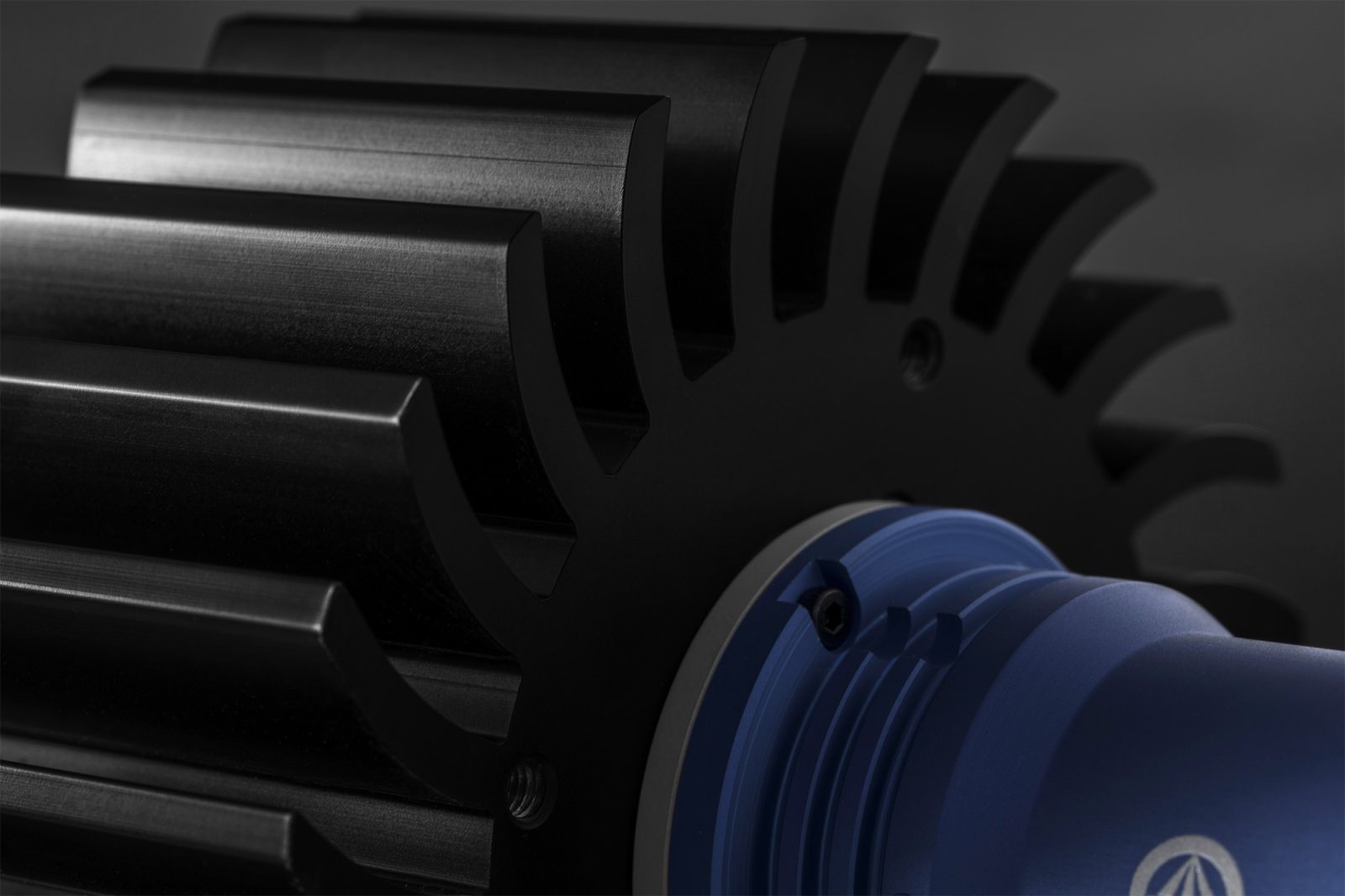
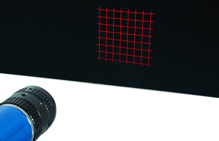
The LTPRXP series features powerful LED pattern projectors designed for inline or offline applications including quality control, 3D reconstruction, dimensional measurement, planarity control, robot guidance and alignment applications.
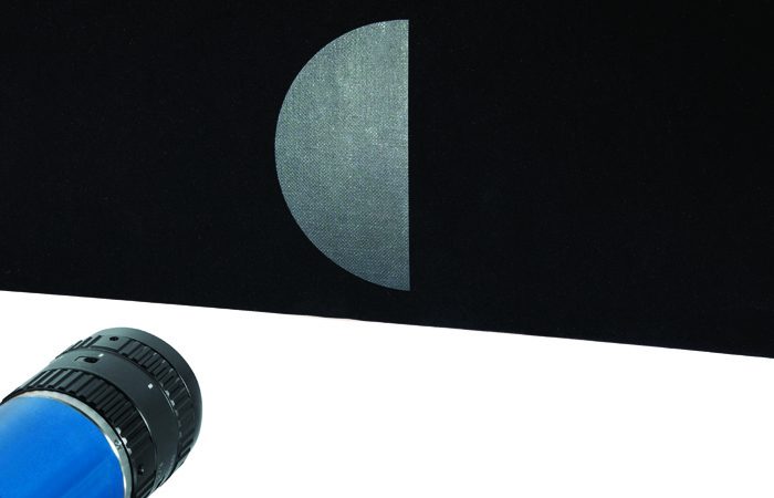
Unlike laser sources, which typically show poor line sharpness and power distribution as well as scattering, speckle and diffraction effects, LTPRXP pattern projectors integrate LED sources and precisely engraved patterns ensuring thinner lines, sharper edges and more homogeneous illumination.
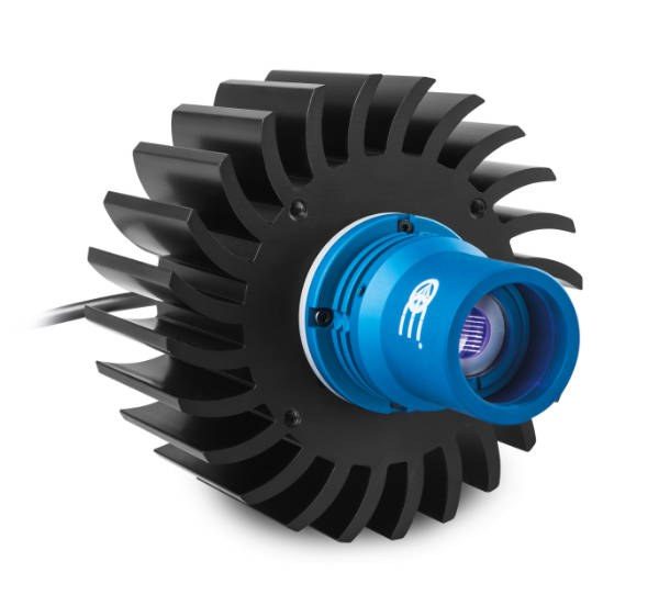
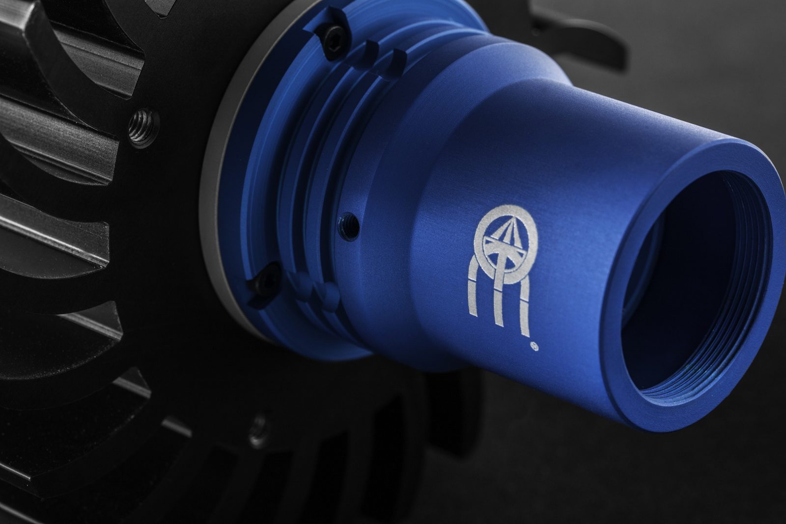
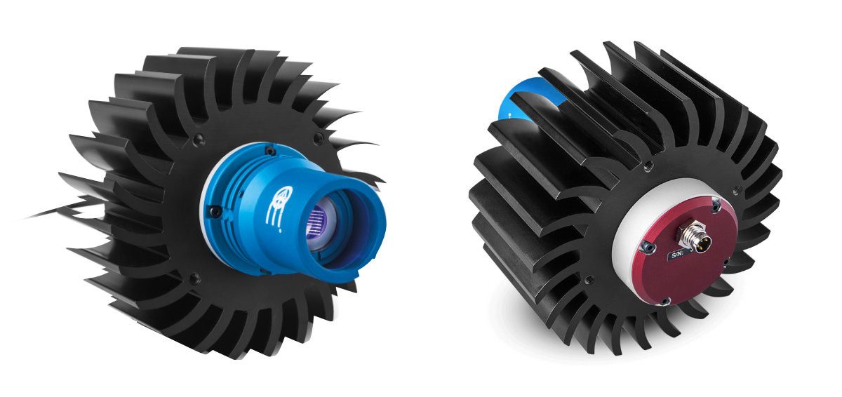
The high power of LTPRXP models decreases the sensitivity of the vision system to ambient light, making these projectors suitable for 3D mapping of objects. Additionally, the LTPRXP models’ large heat sink ensures long lifetime of the LED module and driver electronics, even at the highest power rates.
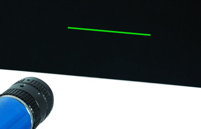
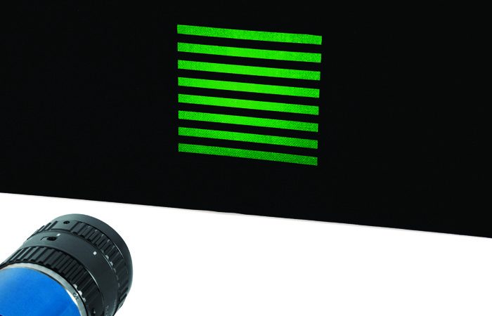
The LTPRXP series is available in different colors and features a wide selection of projection patterns (see PTPR series) which can be easily interchanged to project any kind of shape.
Notes
- With a 35 mm lens, F/N 1.4 at 100 mm working distance without projection pattern at maximum driving current. Estimated value.
- Tolerance ± 10%
- At max forward current.
- Max continuous LED driving current is supplied through the built-in electronics. No external controller is required.
- At 30°C, 700mA.
LTPRXP models are designed for continuous mode and integrate built-in electronics that control the current flow through the LED.
LTPRXP models have fixed current and cannot be dimmed.
LTPRXP-x models featuring built-in electronics, fixed current output and ~ 10W power intensity.
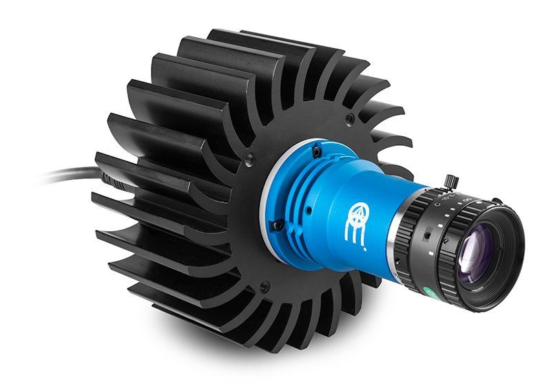
Projection lens selection
C-mount optics for 2/3” sensors (11 mm image diagonal) can be interfaced with LTPRXP series to project areas with different sizes. Unless the projection optics introduces significant distortion, the shape of the projected pattern will preserve the features and aspect ratio of the engraved pattern.
The projected area dimensions will be “M” times the original dimensions of the pattern, where M is the optical magnification at which the selected projection lens is operating.
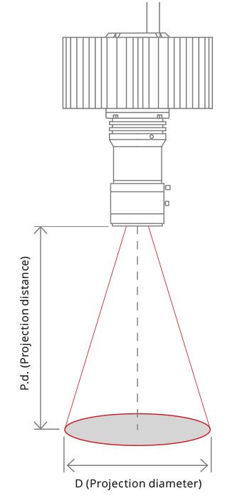
Below follows a list of the projection diameters (D) and the recommended projection distances (P.d.) achieved with different types of optics.
2/3″ C-mount lenses
| P.D. | @50 | @75 | @100 | @150 | @200 | @250 | @300 | @400 | @500 |
|---|---|---|---|---|---|---|---|---|---|
| mm | mm | mm | mm | mm | mm | mm | mm | mm | |
| Focal length |
D (Projection diameter) (mm) |
||||||||
| 6 mm | 81 | 127 | 172 | 264 | |||||
| 8 mm | 58 (*) | 92 | 127 | 195 | 264 | 333 | |||
| 12 mm | 35 (*) | 58 (*) | 81 | 127 | 172 | 218 | 264 | ||
| 16 mm | 41 (*) | 58 (*) | 92 (*) | 127 | 161 | 195 | 264 | 333 | |
| 25 mm | 55 (*) | 77 (*) | 99 (*) | 121 (*) | 165 | 209 (*) | |||
| 35 mm | 68 (*) | 83 (*) | 115 | 146 | |||||
(*) = spacers may be needed to compensate back focal length
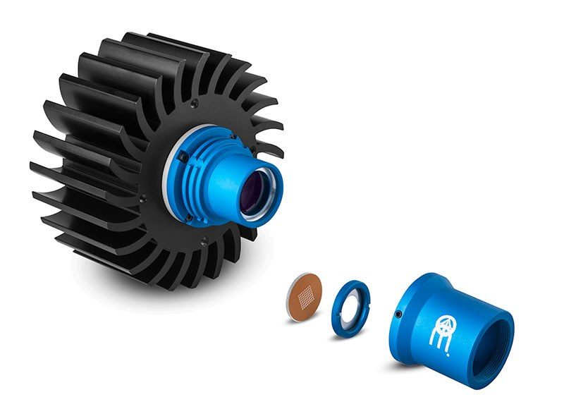
Pattern selection
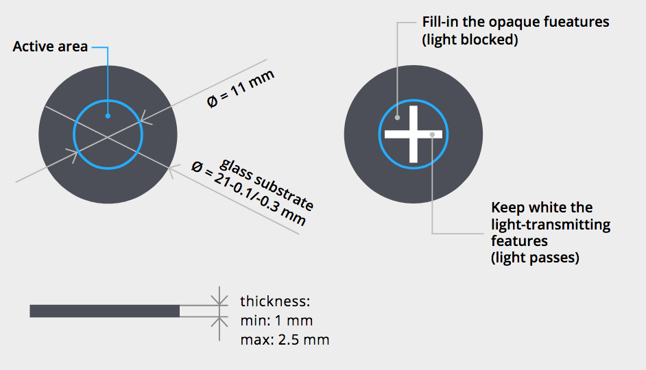
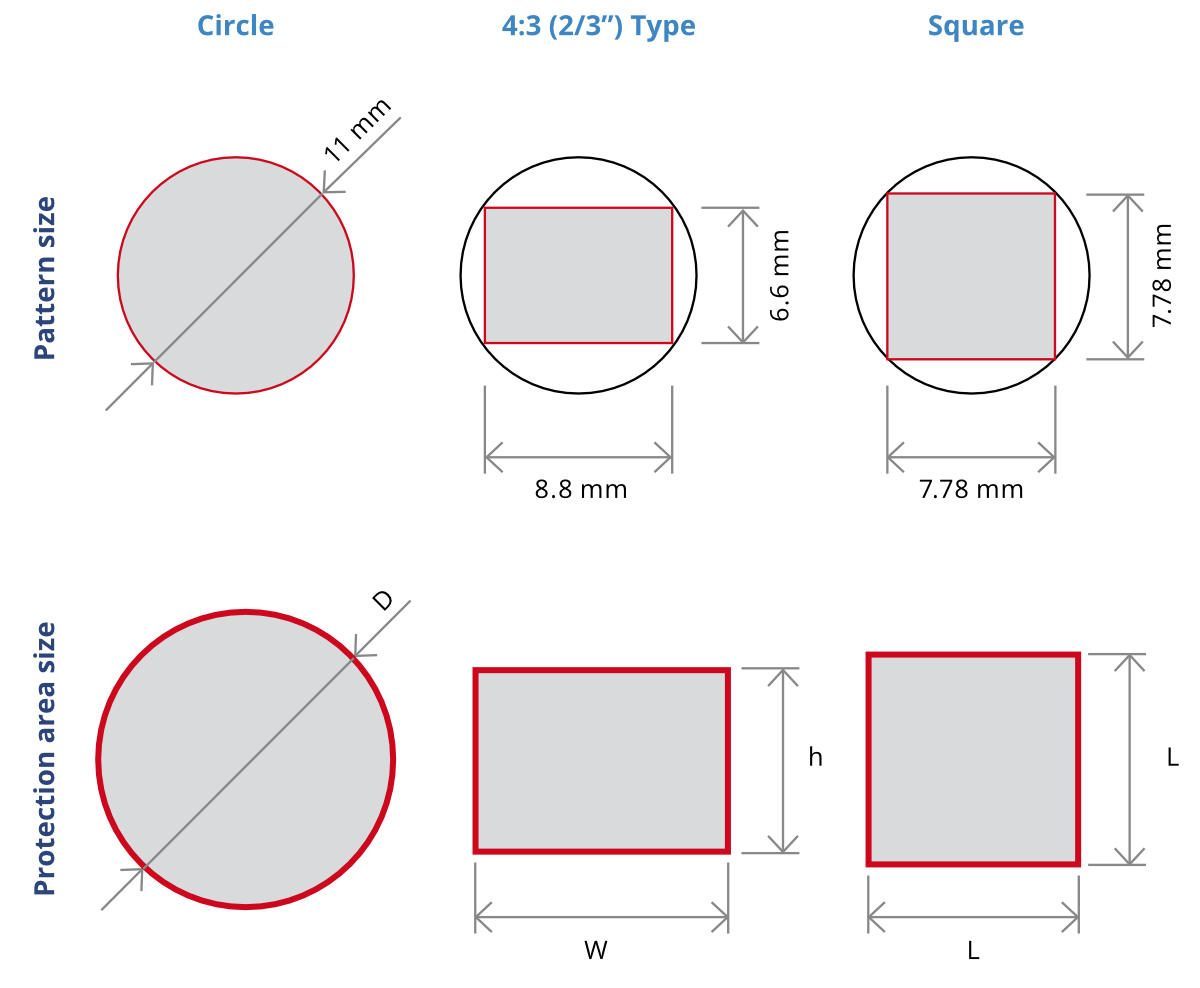
The projection pattern can be easily interchanged by unscrewing the retaining ring that holds the pattern. The pattern outer diameter is 21 mm, while the active projection area is a circle of Ø 11 mm.
The pattern drawing could either cover the entire 11 mm diameter area or be of any shape inscribed within this area (such as a square whose side is 7.78 mm or an 8.8 x 6.6 mm rectangle).
The projection accuracy depends both on the pattern manufacturing accuracy and the distortion of the projection optics mounted on the projector.
The edge sharpness of the projected pattern depends on both the lens resolution and the engraving technique: laser-engraved patterns (part numbers ending in “L”) or photolithography-engraved patterns (part numbers ending in “P”) can be chosen depending on the type of application.
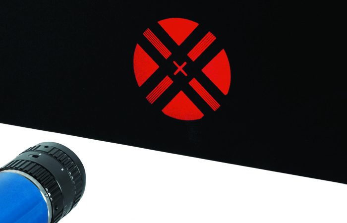
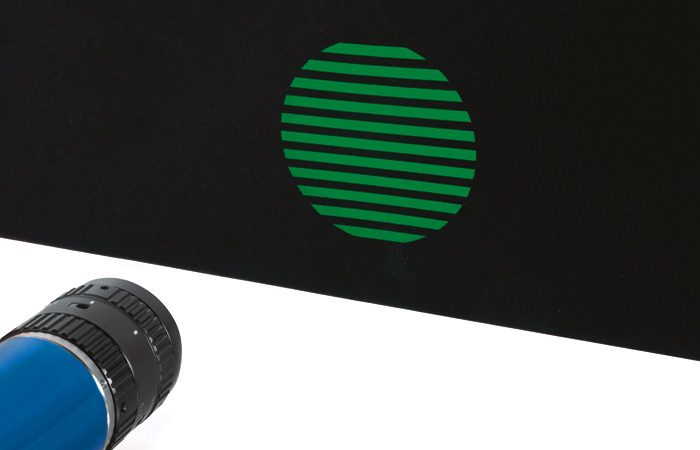
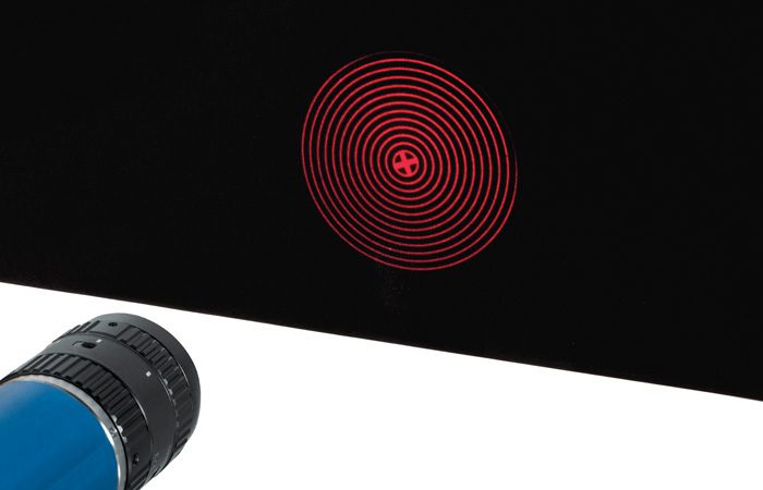
Standard patterns
Custom-made patterns
Custom-made patterns can be supplied on request. A drawing with accurate geometrical information must be submitted (please refer to the instructions here below).