TCBENCH CORE series
Compact telecentric optical benches for precision measurements

Key advantages
- Multi-level cost-cutting
Saves money on manufacturing and transportation costs. - Downsized vision system
Allows to reduce the length of your measurement system. - Pre-assembled setup
Just add a camera and a measurement software and you’re ready to go. - Best optical performances in a super-tight space
A complete optical system designed for hassle-free development of demanding precision measurement applications. - Detailed test report with measured optical parameters.
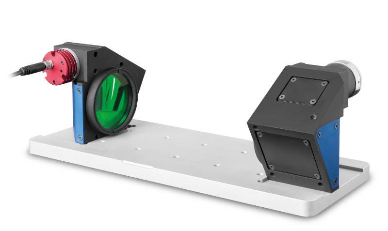
TCBENCH CORE series is a range of complete optical systems offering superior performances needed for highly demanding measurement applications in a super compact assembly.
The benches come pre-mounted and pre-aligned, ensuring the best accuracy that a telecentric measurement system can deliver.
Each TCBENCH CORE integrates:
- 1 TC CORE bi-telecentric lens for 2/3” sensors
- 1 LTCLHP CORE telecentric illuminator (green)
- 1 CMPTCR base-plate
TCBENCH CORE systems deliver the same optical performances as our TCBENCH systems in a very reduced space.
DID YOU KNOW?
The TCBENCH CORE series is now also available with new LTSCHP1W-GZ green light source, suitable for any kind of sample and specifically tailored for measuring reflective objects and objects with sharp edges.
KEY FEATURES
- Reduction of edge diffraction effects.
- Enhanced illumination uniformity, especially on large FOVs.
- Less sensitive to alignment.
Ordering information
To order the version with the new green LED module use part number TCCRBENCH0xx-0-GZ (i.e. TCCRBENCH064-0-GZ).
Notes
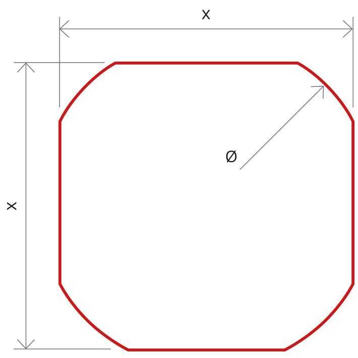
- Indicates the dimensions and shape of image, where "Ø =" stands for diameter and "x=" indicates the nominal image height and length (Tech Info for related drawing).
- Working distance: distance between the front end of the mechanics and the object. Set this distance within ±3% of the nominal value for maximum resolution and minimum distortion.
- Working f-number (wf/N): the real f-number of a lens in operating conditions.
- Maximum angle between chief rays and optical axis on the object side. Typical (average production) values and maximum (guaranteed) values are listed.
- Percent deviation of the real image compared to an ideal, undistorted image. Typical (average production) values and maximum (guaranteed) values are listed.
- At the borders of the field depth the image can be still used for measurement but, to get a very sharp image, only half of the nominal field depth should be considered. Pixel size used for calculation is 3.45 μm.
- Object side, calculated with the Rayleigh criterion with λ= 520 nm
- At max forward current. Tolerance is ± 0.06V on forward voltage measurements.
- Used in continuous (not pulsed) mode.
- At pulse width <= 10 ms, duty cycle <= 10% condition. Built-in electronics board must be bypassed (see tech info).
- Maximum width dimension considering illuminator/telecentric side and cable connector end
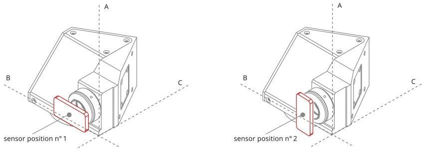
TC CORE lens dimensions (A, B, C) and correct position of the sensor in relation to the lens:
Instructions for use
Operation options
LTSCHP LED modules can be operated in two ways:
- standard usage option: through the built-in electronics
- direct LED control usage option
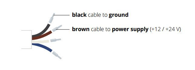
STANDARD usage option (LED control throuh built-in electronics)
Only conitinuous mode (constant voltage) is allowed.
Connection:
Connect the black and the brown cables to your +12 / +24 V power supply.
Light intensity adjustment
The built-in multi-turn trimmer allows to control the light (LED forward current) intensity with a very high degree of precision: you can bring the current intensity from minimum to maximum with 21 full turns of the adjustment screw. Simply remove the protective cap and rotate counter-clockwise the adjustment screw to increase light intensity and vice versa.

LED replacements
Direct LED control usage option
Both continuous and pulsed mode are allowed; the built-in electronics can be bypassed in order to drive the LED directly for use in continuous or pulsed mode. When bypassed, builtin electronics behaves as an open circuit allowing direct control of the LED source. Please note that in such case light intensity adjustment is not possible though the built-in multi-turn trimmer.
Connection:
Connect the black and blue cables as shown below (remove the LED anode protective cover).
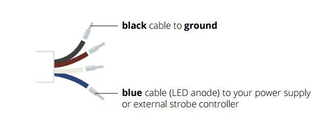
Make sure not to exceed LEDs maximum rates to avoid electrical shorts.

